Hackpad
What is a Macropad?
 A macropad is a mini keyboard with only a few keys. (6 in my case). Now, you might be wondering what a keyboard with only 6 keys is good for, and that's a great question!
It's not really meant to be used as a standalone keyboard, but WITH your existing keyboard! Now you might be wondering why you would ever need a keyboard for your keyboard.
Well, you know how CTRL+C and CTRL+V are copy and paste? There are actually lots of combos like that, and they can be huge timesavers!
I personally use them to do things like open Task Manager, switch between tabs, close windows, open tabs in a new window, render in Blender and SO MUCH MORE!
The best part about a macropad is that it can do anything you want it to! Need it to do a specific mouse action? Done. Need it to type a long string of words that you use a lot? Done.
Need to do a simple key combo? Done! Macropads are such AMAZING tools, so why don't we make one?
Step 1: Designing the PCB
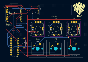
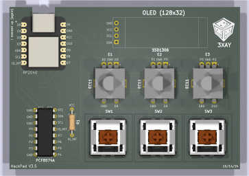
 The very first step is to design the PCB, which was actually my favorite part. I've never actually dealt with PCBs or their designs, so learning that was a challenge at first.
Eventually, with some guides and tutorials, I got the hang of KiCad. I made a few revisions (3 revisions to be exact) of my PCB schematic until I got all of the features I wanted.
While making the schematic, I found it incredibly relaxing to place a few components down and map each individual trace to each component.

The silkscreen on the other hand, was incredibly annoying. After I spent a bunch of time doing the silkscreen, it turns out it was too thin to be printed, so I had to go and redo everything to make sure it was thick enough.
The good part, however, is that in the end, I got a fully functional and fairly aesthetic PCB that I was proud of.
Step 2: Making the Case
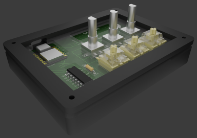
 I'm personally very comfortable in Blender, which is why that's what I used to make my case. The very first problem I faced was importing
the PCB design from KiCad to Blender. It was fairly easy to do in other CAD software, but kinda annoying to do in Blender. Finally,
after a lot of research, I found a tool that converted the PCB to a file that could be imported into Blender. It's by 30350n, you should go check it out.
The only problem with this tool was that the textures, although super high-quality, were incredibly laggy, so I spent a lot of time making my own textures, which is why it doesn't look great.
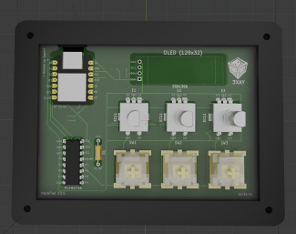
But after the PCB was fully modeled (thanks to PonderSlime for the 3D models for the parts), it was time to design the actual case.
To be honest, I was actually procrastinating a lot because this is the part I got stuck on for my last macropad, so it was a bit scary. Thankfully, I had lots of guides this time,
and it was a much simpler design. I started with the bottom, and then used that to make the switch plate and top plate. I had some problems (I didn't make enough holes in the switch plate)
and I forgot to make the acrylic 3mm thick, but in the end, I caught all of my errors and was done with the plate.
Step 3: Firmware

This is the part that I thought would be the easiest, but oh boy was I wrong. Turns out, firmware is hard, like really hard... Because I had a QMK compatible MCU (Microcontroller Unit), I thought it would be smooth sailing from here, but I seemed to have forgotten that I need to actually set it up.
And the worst part, was that my macropad was incredibly weird. Most people have 0 or 1 knobs, I had 3... Most people don't tend to have a screen, I did... And the most important part is most people tend to use matrix wiring, I used direct wiring... (learn about the difference here). Basically, all of these small problems added up and made it super hard to learn QMK. On top of that, the submission date was almost here and I needed something. I ended up making a custom firmware in CircuitPython, which was pretty rushed.
Step 4: Assembly
My hackpad got shipped, but was missing some parts. Thankfully, I was able to solder the screen (backwards because I messed up the footprint) and 3 encoder switches with 1 rotary encoder working. After a few firmware tweaks, the stuff I had so far was working. Unfortunately my case was half missing, and I didn't have any switches + I/O expander. This was also my first time soldering, so it took a sec. I also didn't have a fume extractor or even a fan at the time so the fumes kept on going straight in my lungs...
WILL NOT BE COMPLETED :(
I've poured a tremendous amount of time and energy into this project, and I've learned a lot and am grateful to Hack Club for providing me this opportunity, HOWEVER, I have noticed that I have made serious design flaws such as a reversed OLED connector and much more. It does not make sense to continue development on this project at this time, given that I no longer have a strong need for a macropad and a future revision with wireless capabilities + my better understanding of PCB design to improve the build and usability. By the way, it did end up working, I just had a missing part + the screen had to be mounted behind the macropad, so the code all worked, just not the full thing.


